Download Input - Electrical Engineering and Computer Sciences - Exam and more Exams Electrical Engineering in PDF only on Docsity!
Electrical Engineering 42/100 Department of Electrical Engineering and Computer Sciences Summer 2012 University of California, Berkeley Instructor: Tony Dear
Midterm Exam: Monday, July 16, 2012
Last Name: First Name:
SID:
Discussion (circle one): 9-11am (Jerry) 10-12pm (John) 12-2pm (William) 2-4pm (Dennis)
Notes and Instructions
- Fill out the information above as clearly and accurately as possible.
- You have 110 minutes to complete this exam.
- This exam contains five questions, on a total of sixteen pages (including this one).
- Do all your work and box all answers on the provided paper; do not hand in loose papers.
- None of the questions require long-winded calculations. Show your work clearly and concisely; partial credit will be given, but unclear or unnecessarily complicated work may be penalized.
- One sheet of notes may be used on this exam.
- You may not communicate with anyone else during the course of the exam, nor are electronic computa- tional devices allowed. Academic dishonesty policies will be enforced.
- Don’t panic... and may the force be with you. :)
I have read all of the above instructions and agree to comply with them. All of the work on this exam is my own, and I had no prior knowledge of the exam contents.
Signature:
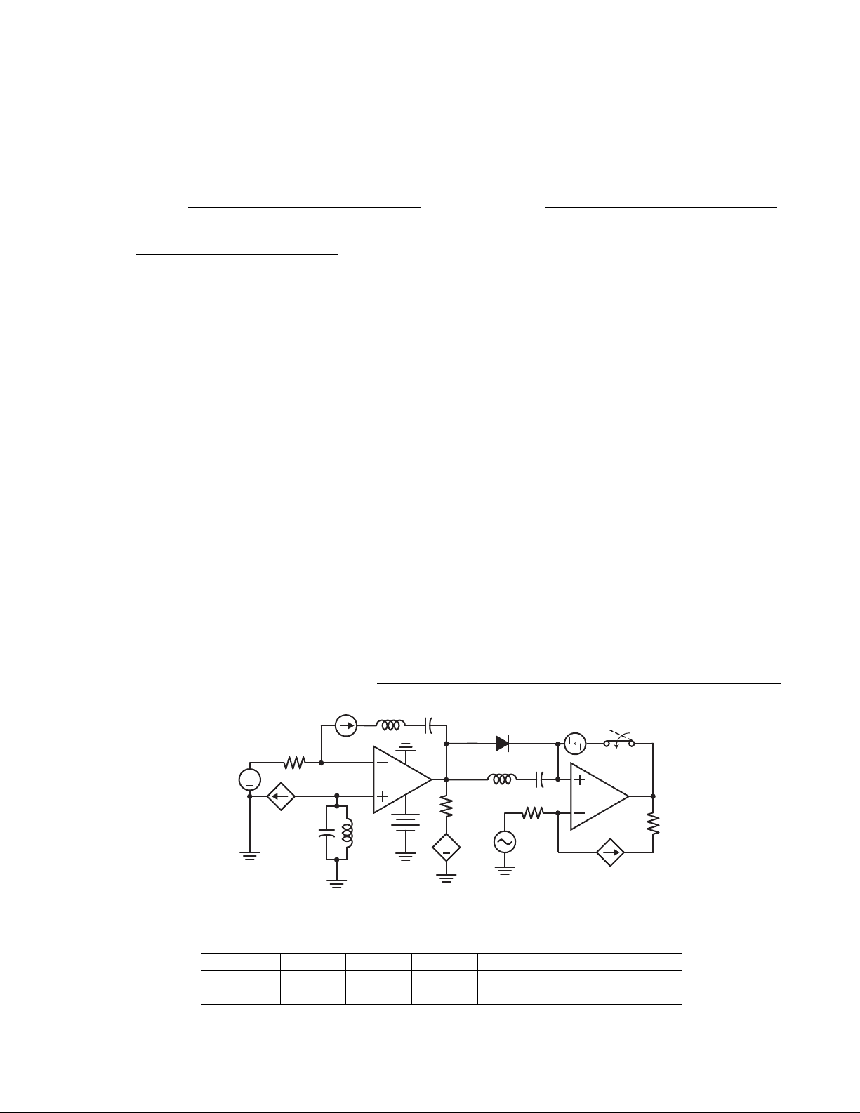
Consider the above circuit... har jk :P
Question Q. 1 Q. 2 Q. 3 Q. 4 Q. 5 Total
Score /25 /15 /15 /25 /20 /
This page intentionally left blank
(b) (10 points) Consider the following circuit.
20 V +
4 F
12 F
3 H
12 F
4 F
2 A
i. Simplify the circuit by applying all possible series and parallel combinations to any resistors, capacitors, inductors.
ii. Assuming DC steady state, calculate the powers of the sources and state whether each is supplying or absorbing energy.
iii. Find the energy stored in the inductor assuming DC steady state conditions.
(c) (10 points) Consider the following RLC circuit. The capacitor is initially uncharged. Express all results below in terms of the given circuit parameters.
Vs +
t = 0
R C
L
vC (t)
i. Derive the ODE governing vC (t) for t > 0 (Vs is a DC source).
ii. Assuming underdamped behavior, qualitatively describe the behavior of vC (t) over time. You may sketch plots to supplement your explanation.
iii. Find an expression for the energy stored in the capacitor after a very long time.
(c) (4 points) Now Tony comes over and says that the lab only has resistor values between 100 Ω and 10 kΩ due to budget cuts. “No problem!” says Jerry. He decides to add a noninverting stage after the first amplifier. Choose new values for all resistors so that we still have a gain of over -9000.
vin
vout
R 1
R 2
R 3 R^4
(d) (2 points) Jerry builds his circuit and finds that it doesn’t work. But of course, he has forgotten to power the amplifier! He attaches supply rails of ±15 V to both op amps. Using the resistance values that you chose above, what is the voltage input range for which amplifier operation remains linear?
vin
vout
R 1
R 2
R 3 R^4
(e) (3 points) Just as Jerry finishes his new design, Tony comes over and says, “Oh btw, the source resistances for the inputs will be on the order of 10 kΩ.” Find the input resistance of the circuit using your resistance values and explain why this is problematic.
(f) (3 points) Tired of the constant spec changes, Jerry ragequits and leaves the problem for Dennis to fix. Help Dennis rectify the new problem by adding another stage to the amplifier circuit to make the input resistance as high as possible without changing the gain.
More space for part (a)...
(b) (3 points) While William has only performed two measurements, he now essentially knows the black box’s current output for any voltage input (or vice-versa). For the references shown below, plot the box’s i-v characteristic. Label axes, intercepts, and slopes.
LINEAR CIRCUIT INSIDE
i
v
a
b
- What Is This I Don’t Even
In an attempt to troll the students, Dennis has constructed the following monstrosity. Both switches close at t = 0, and the capacitor is uncharged prior to the switch actions. Assume that the op amp is ideal with no rail limitations and that negative feedback holds.
5 V 4 H
vo(t)
3 V
0 .2 mF
(a) (8 points) Find v+(t) at the noninverting input for t > 0.
5 V 4 H
vo(t)
3 V
0 .2 mF
(d) (4 points) Does v−(t) ever reach a steady-state value? If so, find the value; if not, explain why this circuit does not allow for this to happen.
(e) (4 points) Does vo(t) ever reach a steady-state value? If so, find the value; if not, explain why this circuit does not allow for this to happen.
- Not Sure If Wrong Figure... Or If GSIs Just Got Lazy
John takes Dennis’s circuit and replaces the input voltages with sinusoidal sources, both with frequency ω = 25 rad/sec. He also wants to find vo(t), though he doesn’t care about the transient response.
5 cos(25t) V 4 H
vo(t)
3 cos(25t) V
0 .2 mF
(a) (5 points) Help John thwart Dennis’s ODE trolling plan by redrawing the circuit with all elements converted to the phasor domain.
V 1
V 2
Vo
Z 1
Z 2
Z 3
Z 4
Vo =
Z 4
Z 3 + Z 4
Z 1 + Z 2
Z 1
V 2 −
Z 2
Z 1
V 1
(c) (4 points) Using the gain given above, derive an expression for Vo, the phasor form of vo(t).
(d) (4 points) Perform the final conversion back to the time domain to obtain an expression for vo(t).
This page is not graded. No fun questions this time because we know that most of you will probably not want to waste your precious time. If you actually do finish early, feel free to use the space below to write, compose, rant, complain, draw, create, etc. We’ll find it encouraging when grading your midterms deep into the night.
We’ll start you off with a Pikachu.